|
General
Thrust reversal assists greatly in bringing an aircraft to a stop after
landing, or in case of an aborted takeoff. Even more so when the wheel
braking effectiveness is reduced by wet or icy runway surfaces. Reverse
thrust on a dry runway represents about 20% of the total braking force, and
up to 50% on a wet or icy runway. Most jet transport aircraft have reverse
thrust capability, inclusion of which lowers the wear and maintenance levels
of the wheel braking units.
Most turboprop aircraft have a form of reverse thrust also. For now we
will concern ourselves with jet engine reverse thrust.
Principle of operation
It is important for you to understand that when reverse thrust is
selected by the pilots, the engine does NOT rotate in the opposite direction
to that when developing forward thrust. Furthermore, it does not now suck in
air at the rear of the engine and blow it out the front. The air is
processed in the normal way and deflected forward at an angle of
approximately 45 degrees, by one of four methods which will be discussed
shortly. Because we cannot efficiently turn the air a full 180 degrees, the
maximum amount of deceleration force will be only approximately 50%-60% of
that which can be developed at full forward power (refer fig BGT 1).
| Limitations on use
Reverse thrust is most effective when used at high runway speeds,
and less effective at low speeds, therefore early selection of reverse
thrust is desirable. Use of reverse thrust at speeds below
approximately 60-70 knots can cause engine damage through sand, stones
and other foreign objects entering the intake having been initially
lifted off the runway by the forward flowing air. Surging (compressor
stall) is also a possibility as the hot exhaust air is re-ingested at
the intake.
Normally a throttle setting of about 75% N1 speed is used during
reverse operations, 100% N1 in an emergency such as a high speed
rejected takeoff near V1 (refer fig BGT 2).
Reverse thrust can NOT be deployed will in flight, except on a few
aircraft such as the Douglas DC8. |
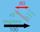
Fig BGT 1. Reverse thrust vector.
|
| Reverse thrust selection
To select reverse thrust there must first be weight on the wheels. This
is sensed through ‘squat switches’ on the main undercarriage. Secondly,
the thrust lever must be in the ‘idle’ position. Only when these two
pre-requisites are satisfied will an isolation valve open to permit reverse
thrust activation. |
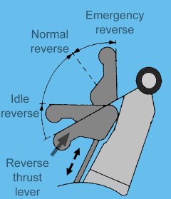
Fig BGT 2. Reverse thrust lever movement.
|
Disadvantages of thrust reversers
Actuation
This is normally achieved using pneumatic bleed air taken from
the engine compressor, though the ‘bucket’ type uses hydraulic
actuation.
Reverse thrust types
| Bucket
type: This is also known as ‘target type’, and is
hydraulically actuated. In the forward thrust position the thrust
reverser buckets form the convergent/divergent exhaust nozzle of the
engine. In the reverse position the buckets deflect the hot exhaust
gasses forward (refer fig’s BGT 3a and 3b).
|
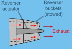
Fig BGT 3a. Bucket doors in the forward thrust
position.

Fig BGT 3b. Actuator and buckets in the
reverse position. |
| Clamshell type:
This is a pneumatically operated type using bleed air from that
engines compressor.
The clamshell doors form part of the exhaust tailpipe when in the
forward thrust position. When reverse thrust is selected, the
pneumatic actuators move the clamshell doors so as to block the
escape of exhaust gases, and deflect them forward through forward
angled ‘cascade vanes’. These are only exposed when the
clamshell doors move toward the reverse thrust position. Like the
bucket type, the clamshells operate in the very hot and high
velocity exhaust gas stream, and so must be built of very sturdy
heat resistant metal alloys.
(refer fig BGT 4a and 4b)
|
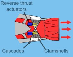
Fig BGT 4a. Forward thrust position.
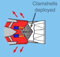
Fig BGT 4b. Reverse thrust position.
|
| Fig 5
shows an external view of cascade vanes exposed as translating sleeve
moves rearward.
|
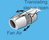
Fig BGT 5. Translating sleeve open.
|
| Fig’s 6a,
6b, and 6c show the progression from forward to
reverse thrust on a General Electric CF6 engine as fitted to a Boeing
B767. Note the EICAS annunciations when blocker doors are in transit, and
when locked in reverse thrust position. |

Fig BGT 6a. Forward thrust position.
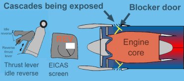
Fig BGT 6b. Reverse thrust selected, blocker doors in transit.
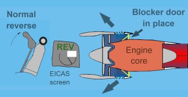
Fig BGT 6c. Blocker doors in place.
|
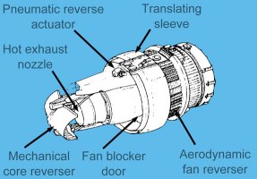
| Bucket/cold stream
combination: This is effectively a hybrid design being both a hot
and cold stream reverser in one (refer fig BGT 7). |
 |
Thrust reversal is intended for use
on the runway, though it can be used to reverse the aircraft from the airport
terminal gate. This is NOT recommended practice as it puts ground staff at risk,
can cause engine surging and foreign object damage, and it is difficult for the
crew to steer safely as they cannot see where they are going. If a ground tug is
available for the pushback, use it.
Hopefully this mini editorial on thrust reversers will
help you understand the general principles of interest to pilots. It is an
extract from the training manual called “Basic
Gas Turbines for Pilots”, which will be of interest to those
planning to fly jets, or studying towards there ATPL examination. You can
purchase this book from the ONLINE SHOP
within this website, or at one of the many approved distributors
around Australia.
Avfacts ATPL
training course information is also available in this site, as
are some practice examination
questions on various ATPL subjects.

Finally, good luck with your studies, and remember ...
"Pilots are
always learning"
Best Wishes
Rob Avery

Marty says ... "Goodbye to GA".
|


