| General
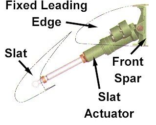
High lift devices for takeoff and landing are provided each wing by 5
outboard and 1 inboard slat section, plus slotted Fowler trailing edge
flaps. Additionally, the inboard ailerons droop with the trailing edge
flaps.
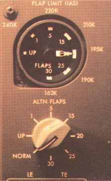
Flap positions are UP, 1, 5, 15, 20, 25, 30. The 25 and 30 are landing
flap selections.
Normal Operation
Under normal operations, the flaps and slats are operated by a single
flap selector lever to the right of the thrust levers. Moving the flap
lever to one of the flap detent's sends signals to 3 Power Drive Unit (PDU’s),
which in turn move the flaps and slats.
One PDU drives the inboard leading edge slats. Another drives the 5
outboard slat sections. A third drives the trailing edge flaps. Power to
all is supplied from the centre hydraulic system
.
| Flap/Slat position
indicators
A cockpit dial with two pointers (left and right) shows the
actual flap position. If left and right flaps/slats are moving
correctly and in unison, the left point obscures the right point
beneath it. The dial is used to identify the flap/slat position,
during takeoff, approach and landing checks, along with the flap
handle position itself.
- In the UP position, both the leading edge
slats and trailing edge flaps are retracted.
|
- In position 1, the leading edge flaps are
extended to the takeoff position. Trailing edge flaps
remain retracted.
|
- Moving the flap lever to the 5, 15, 20
detent's, drives the trailing edge flaps accordingly. The
leading edges stay in the takeoff position.
|
- Moving the flap lever to the 25 or 30
(landing flap) positions simultaneously moves the leading
edge slats and the trailing edge flaps to the landing
position.
|
| Non-Normal operation
Alternate slat/flap movement is provided by electric
motors, one connected to each of the PDU’s. Normal hydraulic
power is by-passed. Pressing either or both the leading edge
or trailing edge alternate flap switches allows the pilot to
select flap using the alternate flap selector knob, which is
next to the flap position indicator dial.
Flap movement is much slower using the alternate (electric
drive) system. It takes about 3 minutes to drive the flaps
from the UP position to the 20 degree position.
Flap asymmetry and flap load relief protection are NOT
provided when using the alternate system. The NORM position on
the alternate flap selector switch is when normal hydraulic
system operation is occuring.
Flap load relief system
Once the landing flap setting of 25 degrees has been
selected, any over-speeding of the flap upper limit speed
causes the trailing edge flaps to retract automatically to the
20 degree setting, thereby protecting the flaps from becoming
over-stressed by air loads.The flap position indicator will
show the change, but the flap lever position will NOT change,
remaining in it’s original position. Once the speed has
reduced to below 25 flap limiting speed, the flaps
automatically extend to the lever commanded position. |
|
|
Flap/slat asymmetry protection
Should the leading edge slats, or trailing edge flaps on one wing move
at a different rate to that of the corresponding unit on the other wing,
the flaps/slats will cease to move any more under the normal hydraulic
system. You could use the alternate system but it is not recommended, as
there is no asymmetry protection afforded by the alternate system.
Asymmetric flap/slat is a serious threat, as this can cause uncorrectable
roll due to the different lift being developed by each wing. You may have
to land with whatever flap was lowered when asymmetric flap first was
sensed.
Leading edge or trailing edge disagreement
If either the flaps or slats are NOT driving toward their commanded
position, a warning light illuminates, and an EICAS message appears. Slats
and flaps can be moved using the alternate system.
I hope this mini-editorial assists you in the ATPL Aerodynamics and
Aircraft systems examination.
The next editorial will look at hydroplaning, which is part of the same
examination.
Until then, happy flying !
Rob Avery
ATPL Lecturer

Marty says ... "Goodbye to GA".
|


