|
|
|
|
Aircraft Systems Topic 13.
Boeing 767 Flight
Controls
Part 3: Elevators & Rudder
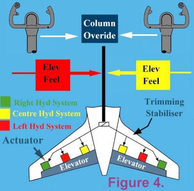
| Elevators
Moving either of the control columns sends signals to the three hydraulic actuator which move the elevators. All three hydraulic systems (Left, Centre, and Right) power the elevators. Each of these hydraulic systems are completely separate and self-contained. Left and right elevator position is shown on the lower EICAS status display, and full and free movement of the elevators is confirmed through this display, prior to takeoff. Two hydraulically powered elevator feel systems provide artificial feel forces to the pilot’s control columns. These are powered by the left and centre hydraulic systems. Mechanical springs provide feel, following the loss of both left and right hydraulic systems (refer fig 4). A column override facility ensures positive flight control authority should one control column jam. Stabiliser The stabiliser is positioned by dual trim control modules, which use hydraulic power from the left and centre hydraulic systems to re-position the stabiliser through a motor and brake mechanism. The motors move the stabiliser to any newly commanded position, and the associated brakes hold the stabiliser in that position, until a new position is commanded. Stabiliser position is shown on indicators either side of the control stand, just like in light aircraft. The green trim position band indicates the normal range of trim settings for takeoff. The pilots position the elevator trim from centre of gravity position information contained on the load and balance sheets, as provided by the Load Controller. The actual rate of trim varies with airspeed, such that at increased airspeed reduces the trimming rate. Speed inputs come from the Central Air Data Computer (CADC). There are three modes of stabiliser trim control:
Mach trimmer The stabiliser is also responsible for increments of nose up trim application to prevent “TUCKUNDER”, (also called “MACHTUCK” ) when operating around transonic flight speeds. Non-normal Operation If one autopilot only is engaged, operation of the yoke mounted trim switches causes the autopilot to disengage. If multiple autopilots are engaged (ie: when on approach below 1, 500 ft agl), the yoke mounted electric trim switches are de-energised and thereby operation of these is inhibited. Manual/Alternate trimming does NOT cause the autopilot(s) to disengage. Any un-scheduled trim condition is detected when the stabiliser moves without having received a new trim signal, or if the trim is moving in the opposite direction to that commanded by the autopilot. A stabiliser trim warning light illuminates, and an EICAS message appears whenever this condition is detected. The pilot can stop un-commanded stabiliser movement by using the trim cutoff switch, or moving the control column in the opposing direction to stabiliser movement. Should a stabiliser trim brake fail to release while the pilot is operating the electric trim switches, a “STAB TRIM” EICAS advisory message appears, and continued use of the electric trim switches will produce a trim rate at one half normal rate. If the malfunction is unique to the electric trim control, full trim rate is available by using the manual trim levers. If both stabiliser brakes remain engaged, no stabiliser trim is available. Loss of both left and centre hydraulic systems will automatically trigger a shutoff valve, and permit the right hydraulic system to power the stabiliser trim through a “Pitch Enhancement System” (PES). Trim rate is only one quarter that of the normal system, and only the electric trim switches will be operative (ie: the manual, and automatic trim will NOT be operative).
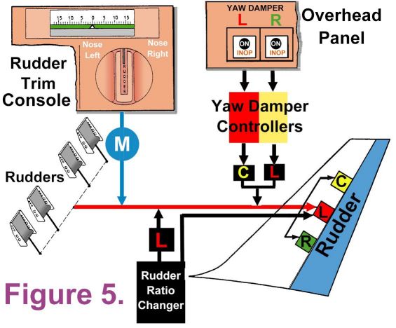
Rudder trim Pushing either set of rudder pedals sends signals to the three separate rudder hydraulic actuators. Two yaw dampers operate through the rudder control system to prevent dutch roll developing, obtain co-ordinated (no slip) turns, and generally improve directional stability. Position of the rudder is indicated on the lower EICAS screen, and is monitored prior takeoff to check that full and free movement is occurring, as the crew cannot see the tailplane from the cockpit. Rudder trim is obtained by turning the rudder trim knob just like in a light aircraft (refer fig 5). An electric motor re-defines the rudder neutral point. Control inputs from the rudders and trim control are modified to take account of the forward speed of the aircraft by a “RATIO CHANGER”. An airspeed input signal is sent to the ratio changer from the CADC, and rudder deflections progressively reduced as the speed increases. If rudder deflections are not being correctly modified by the ratio changer, a “Rudder Ratio Light” illuminates, and an EICAS advisory message appears. When a rudder ratio changer fault develops, the left hydraulic system to the rudder is depressurised to restrict rudder deflection, and thereby provide rudder structural protection at high airspeeds. Sufficient rudder authority is preserved in this case for low speed operation, though more restrictive crosswind and autoland limits apply. Yaw Dampers Two independent yaw dampers operate continuously in flight. Each system has a yaw damper controller which in turn generates signals sent to the rudder actuators. When the yaw damper switches are “ON”, and the amber yaw damper lights are extinguished, the systems are powered, and no fault exists. When electrical power is initially established, an electrical self test occurs. The crew check the entire yaw damper system by moving the yaw damper test switch momentarily to the “LEFT” or “RIGHT”. At least 1 of the 3 Inertial Refence Systems (IRS) must be aligned for the 10 second test to occur. If either of the two “YAW DAMPER INOP” lights remain illuminated after the tests, a fault has been detected. The yaw damper control switches are on the overhead panel, above the pilot’s heads. Loss of one yaw damper reduces rudder yaw authority by one half. I hope this mini editorial is of assistance to you in your studies. See you next time ! Best regards Rob Avery ATPL Lecturer P.S. Some new ATPL texts are due for release early 2000. More on that towards the end of 1999.
|
![]()