|
|
|
|
Aircraft Systems Topic 12.
Boeing 767 Flight
Controls
Part 2: Ailerons & Spoilers
| General
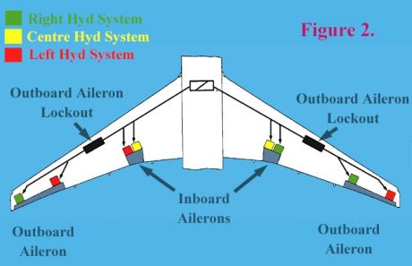
Roll control on the B767 is accomplished by ailerons and wing spoiler panels. Movements of both are activated by rotating either of the pilot control columns. The inboard ailerons droop in conjunction with the trailing edge flaps. Ailerons Like most other high speed aircraft, the B767 features both inboard and outboard ailerons. Both operate in unison at low speed, but as speed increases an aileron lockout device gradually restricts the movement of the outboard ailerons, leaving the inboard types to effect roll at high airspeed. Speed signal inputs for this come from the Central Air Data Computer (CADC). This assures the required roll authority at low speeds, and prevents overcontrolling at high speeds. A warning system advises pilots of lockout device failure, such that at high speeds (around cruise speed) a warning may indicate that one or both of the aileron lockouts have failed to lockout the movement of the outboard ailerons. A failure indication at low speeds (around approach speeds) may indicate that one or both of the lockouts have failed to unlock the outboard ailerons. This will effect the low speed roll control characteristics of the aircraft, and reduce crosswind landing capability. Each aileron is powered by two hydraulic systems for redundancy purposes should one hydraulic system fail. Each aileron is moved by two separate hydraulic actuators. Refer to figure 2. Aileron position is shown on the lower EICAS screen, and is referenced by the pilots when checking control movements prior to takeoff (ie: “controls full, and free”). The ailerons can be trimmed using trimming switches in the cockpit. This re-sets the aileron neutral point. The current aileron trim position is displayed to the pilots on an “aileron trim position indicator” on each control column.
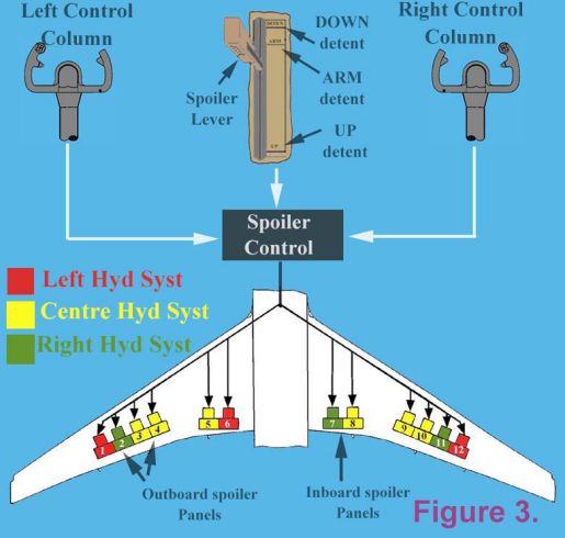
Spoilers/Speedbrakes/Liftdumpers Spoilers are controlled through a speedbrake lever which is to the left of the thrust levers. There are six spoiler panels on each wing upper surface (refer figure 3). Each spoiler panel has it’s own hydraulic actuator, which fed by one of the three hydraulic systems (ie: Left, Centre, and Right). Specific spoiler panels on each wing operate in unison with the ailerons to effect roll control. Roll spoilers are signaled to operate by rotating either control column. Moving the speedbrake lever to the “UP” position in flight allows the spoiler panels to be used as speedbrakes while in flight. This is very handy to both slow the aircraft, or increase the descent gradient, or both simultaneously. Sort of a “get out of jail card”.
Inputs from the control wheels and speedbrake lever are sent to a spoiler controller, which combines the two signals to determine the required spoiler panel deflection, and then signals the spoiler panels to operate. On the ground, all panels deploy as ‘Liftdumpers’ to spoil any residual lift at touchdown, avoid bouncing, and place more weight on the wheels to assist in wheel braking effort. The amount of spoiler deflection is greater on the ground than it is while in flight. Moving the speedbrake lever to the “ARMED” position signals the spoiler controller to extend all spoiler panels after landing. As this occurs the speedbrake lever moves to the “UP” position. Three conditions must occur before the panels will move to the up position. 1. There is hydraulic pressure to both landing gear bogie tilt actuators. 2. Both of the bogie tilt sensors have detected a ‘NO TILT’ condition (ie: the aircraft is on the ground). 3. Both thrust levers are in the “IDLE” position. After automatic speedbrake extension, if either of the three conditions are no longer met, the speedbrake lever and spoiler panels move to the “DOWN” position again. If the speedbrake lever is NOT in the “ARMED” position, but all three conditions are met, and reverse thrust is applied, the spoilers will automatically extend, and the speedbrake lever will move to the “UP” position. In the event of a auto speedbrake fault, the crew are advised through a speedbrake light illuminating, and an amber coloured EICAS advisory message of “AUTO SPEEDBRAKE”. Such a fault may result in loss of automatic speedbrake extension, which could add significantly to the landing distance required. If the speedbrake lever is in the “ARMED” position, and a speedbrake fault occurs, the light and EICAS message indicate a fault which may result in an inadvertent speedbrake extension while in flight. In this case the speedbrake lever should be placed in the “DOWN” position. Speedbrakes can still be extended and retracted manually. Take note of the way the 3 hydraulic systems are hooked up to the various control surfaces to gain an appreciation of the way system redundancy is provided, ensuring that a single hydraulic system does NOT adversely effect safety. Coming mini editorials will address the other flight control sub-systems of Elevators and Rudder, and Flaps and Slats. I trust this mini editorial is of assistance to you, and good luck with your examinations. Remember: Where other pilot’s “ASSUME”, professional pilot’s “CHECK” ! Best wishes Rob Avery ATPL Lecturer
|
![]()